Java 3D API Specification
Java 3D API Specification
| A P P E N D I X |
|
Equations |
This appendix contains the Java 3D equations for fog, lighting, sound, and texture mapping. Many of the equations use the following symbols:
· Multiplication Dot product or function operator E.1
Fog Equations
To be supplied.
E.2
The ideal lighting equation is as follows:


Note: If (Li · N)0, then diffi and speci are set to 0.

Note: For directional lights, atteni is set to 1.

Note: If the vertex is outside the spotlight cone, as defined by the cutoff angle, spoti is set to 0. For directional and point lights, spoti is set to 1.
This is a subset of OpenGL in that the Java 3D ambient and directional lights are not attenuated and only ambient lights contribute to ambient lighting.
The parameters used in the lighting equation are as follows:
E = Eye vector Ma = Material ambient color Md = Material diffuse color Me = Material emissive color Ms = Material specular color N = Vertex normal shin = Material shininess The per-light values are as follows:
Fallbacks and Approximations
1. An implementation may approximate the specular function using a different power function that produces a similar specular highlight. For example, the PHIGS+ lighting model specifies that the reflection vector (the light vector reflected about the vertex normal) is dotted with the eye vector, and that this dot product is raised to the specular power. An implementation that uses such a model should map the shininess into an exponent that most closely matches the affect produced by the ideal equation.
2. Implementations that do not have a separate ambient and diffuse color may fall back to using an ambient intensity as a percentage of the diffuse color. This ambient intensity should be calculated using the NTSC luminance equation:
- I = 0.30 · Red + 0.59 · Green + 0.11 · Blue
E.3
There are different sets of sound equations, depending on the use of headphones or speakers.
E.3.1
For each sound source, Java 3D calculates a separate left and right output signal. Each left and right sound image is made up of the an interaural intensity and an interaural delay. The calculation results are a set of direct and indirect (delayed) sound signals mixed together when sent to the audio playback system left and right transducers.
E.3.1.1
For each point and cone sound source node, the left and right output signals are delayed based on the location of the sound and the orientation of the head. This time difference between these two signals is called the interaural time difference (ITD). This time delay of a particular sound reaching the far ear is affected by the shadow of the listener's head. Java 3d uses an approximation of the ITD using a spherical head model. The interaural path difference is calculated based on the following cases:
1. For sound source "near" parallel sound incidence (Dh > De/2) - See Figure E-1:
- Ec = |Vc|
Ef = Ec + P
- P = De · ((
+ sin
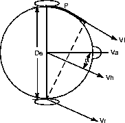
Figure E-1
Distance Source Nearly Parallel Sound Incidence
2. For sources close to the head with the signal reaching one ear by a direct path (sin
- Ec = |Vc|
Ef = Ec + P
- P = De · [(m + 1/2) · cos
+ 1/2(
sqrt(ms + m + 1/2 - ((m + 1/2) · (De/2Dh)) ) ]
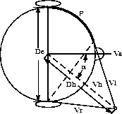
Figure E-2
3. For sound source very close to the head so that the signal reaches both ears by indirect paths around the head (sin
- Ec =
Ef = Ec + P
- P = De ·
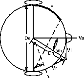
Figure E-3
The parameters used in the ITD equations are as follows:
The time from the sound source to the closest ear is Ec/S, and the time from the sound source to the farthest ear is Ef/S, where S is the region's speed of sound.
E.3.1.2
For each active and playing Point and ConeSound source, s, separate calculations for the left and right signal (based on which ear is closest and which is farthest to the source) are combined with non-spatialized BackgroundSound to create a stereo sound image.
Note: For BackgroundSound sources ITD() is an identity function so there is no delay applied to the sample for these sources.
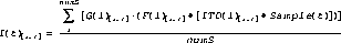
G[l,r] = Gi · Gd[Ec,Ef] · Ga(
Note: For BackgroundSound sources Gd() = Ga() = 1.0. For PointSound sources Ga() = 1.0.
F[l,r] = Fd[Ec,Ef]Fa(
Note: For BackgroundSound sources Fd() and Fa() are identity functions. For PointSound sources Fa() is an identity function.
If the Sound source is on the right side of the head, Ec is used for left G and F calculations and Ef is used for right. Conversely, if the Sound source is on the left side of the head, Ef is used for left calculations and Ec is used for right.
The parameters used in the IID equations are as follows:
E.3.1.3
The frequency of sound waves emanating from the source are lowered based on the speed of the source in relation to the listener, and the sound wave length, as follows:
- S(f)' = S(f) - [Ds · (Dv/W(f,Dh)]
The parameters used in the Doppler effect equations are as follows:
E.3.1.4
To be supplied.
E.3.1.5
To be supplied.
E.3.2
Different speaker playback equations are used, depending on whether the system uses monaural or stereo speakers.
E.3.2.1
The equations for headphone playback need only be modified to output a single signal, rather than two signals for left and right transducers. Although there is only one speaker, distance and filter attenuation, Doppler effect, elevation and front and back cues can be distinguished by the listener and should be included in the sound image generated.
E.3.2.2
In a two speaker playback system, the signal from one speaker is actually heard by both ears and this affects the spectral balance and interaural intensity and time differences heard by each of the listener's ears. Cross-talk cancellation must be performed on the right and left signal to compensate for the delayed attenuated signal heard by the ear opposite the speaker. Thus a delayed attenuated signal for each of the stereo signals must be added to the output from the equations for headphone playback.
The equations for stereo speaker playback assume that the two speakers are placed symmetrically about the listener (at the same off-axis angle from the viewing axis at an equal distance from the center of the listener's head).
- I(t)l' = I(t)l + [D(t)
The parameters used in the cross-talk equations, expanding on the terms used for the equations for headphone playback, are as follows:
E.4
To be supplied.


Java 3D API Specification
Copyright © 1997, Sun Microsystems, Inc. All rights reserved.