
This document describes the VRML 2.0 implementation of IBM's Geometric Compression Technology. Only the data structures, and the corresponding decompression algorithm are specified. Compression algorithms are not part of this specification.
The theory behind IBM's Geometric Compression Technology and the details of the associated data structures, compression, and decompression algorithms are discussed in the paper:
"Geometric Compression through Topological Surgery"
by Gabriel Taubin and Jarek Rossignac,
IBM Technical Report RC-20340, 01/16/96
Section The CGD Data Structure is a short overview of how a polyhedral meshe is represented in the CGD Data Structure.
Section The CGD Decompression Algorithm is a description of how a polyhedral mesh can be reconstructed from the information stored in a CGD Data Structure.
Section The CGD Quantization and Encoding of Data Records is a description of the quantization and encoding of the geometric properties such as coordinates, colors or normals.
Section The CGD Data Structure Syntax is the formal specification of the VRML 2.0 implementation.
A triangular mesh is represented in the CGD Data Structure by one vertex tree, and one or more triangle trees. The vertex tree spans the graph defined by the edges and vertices of the mesh. The compression process cuts the triangular mesh through the edges of the vertex tree, also called cut edges, producing a cut triangular mesh without internal vertices. The dual graph of this cut triangular mesh is described by the triangle trees.
If the triangular mesh is simple (i.e., a topological sphere), one triangle tree is sufficient, because in this case the cut triangular mesh is a simple polygon. The boundary of the polygon is called the bounding loop. Each edge of the vertex tree corresponds to two edges of the bounding loop. This correspondence determines which pairs of edges of the bounding loop must be stiched together by the decompresion process to recover the original mesh.
 |
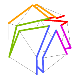 |
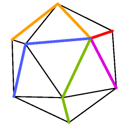
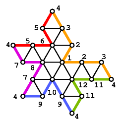
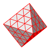
For example, Figure 1 A shows a simple triangular mesh with a vertex tree composed of the colored edges. Figure 1 B shows the resulting cut triangular mesh with the bounding loop composed of the colored edges.
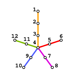
The vertex tree is represented in the CGD Data Structure as a sequence of vertex runs. A vertex run is a path of the tree that connects a leaf or branching node to another leaf or branching node without crossing any other branching node. For example, the vertex tree of Figures 1 A and 1 C has five runs, each one shown in a different color. Choosing a leaf node as the vertex tree root determines a start and end nodes for each run. An orientation of the simple mesh determines a cycling order for the runs adjacent to a branching node. Using a depth-first traversal of the vertex tree we can determine an order of traversal of the runs. Each vertex run is represented in the CGD Data Structure by a last bit, a length value, and a leaf bit. The last bit indicates if the run is the last run to be traversed among those that start at the same node (i.e. the rightmost sibling). The length of a run is the number of edges from the start to the end nodes. The leaf field indicates if the run ends in a leaf.
 |
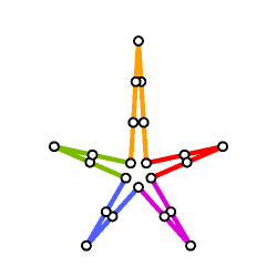 |
Figure 1 C shows a schematic representation of the vertex tree, with each run in a different color, and the nodes ordered according to the order of traversal of the vertex tree. Figure 1 D shows a schematic representation of the bounding loop associated with the vertex tree of Figure 1 C.
 |
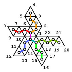 |
Figure 1 E shows the cut mesh unfold in a plane, and figure 1 D shows the dual graph of this simple polygon superimposed onto the cut mesh.
Note that the information contained in the sequence of vertex runs is sufficient for the decompression process to reconstruct the bounding loop. If the triangular mesh is not simple, the bounding loop is not defined by the cutting process described above, but by the sequence of vertex runs.
If the triangular mesh is not simple, the cut triangular mesh is not a simple polygon, but it can be decomposed into a set of one or more simple polygons, each of them described by one of the triangle trees. In this case the bounding loop is not the boundary of any of the polygons. The boundary edges of the polygons that are not on the bounding loop are call jump edges, because they jump from one bounding loop node to another bounding loop node. The internal edges of each of the polygons are called marching edges.
The dual graph of each of the simple polygons is one of the triangle trees which is described in the CGD Data Structure similarly to how the vertex tree is described. However, no last bit value is needed because the triangle trees are binary.
A triangle run of length N can be triangulated in many
different ways. The length value and leaf bit do not
contain contain sufficient information to reconstruct the triangles.
Since each triangle run has a left and right boundaries composed of
contiguous edges of the bounding loop, one bit per triangle is
sufficient to construct the next triangle in the run by advancing to
the next bounding loop node either on the left or the right boundary.
The last triangle of the run may require special treatment. Either
one of the two exposed edges of the last triangle of the run may or
may not be a jump edge. If the triangle mesh is not simple, two bits
are used to indicate if the left and right exposed edges of the last
triangle are jump edges or not, and depending on the values of these
bits either zero, one or two jump values are also added to the
triangle run. Nonorientable meshes may also require one or two extra
An IndexedFaceSet which is not composed of triangular faces, i.e., a polygonal mesh with simply connected faces, is represented in the CGD data structure as a triangular mesh with additional information that indicates which edges of the triangular mesh are edges of the polygonal mesh, and which ones are not.
An IndexedLineSet is represented in the CGD data structure as a subset of edges of an IndexedFaceSet.
A PointSet is represented in the CGD data structure by a vertex tree and no triangle trees.
An Interpolator is represented in the CGD data structure as part of the IndexedFaceSet, IndexedLineSet, or PointSet that it is connected to.
Decompressing a simple mesh involves the following steps, explained in detail below:
The total number V of vertices is the sum of the lengths VLENGTH of the vertex runs plus one. The vertex coordinates are reconstructed from the encoding of the vertex tree. For this, the vertex tree is traversed (depth-first) using a recursive procedure. During the tree traversal an array of indices to ancestors of vertices is maintained. After entropy decoding the vertex position corrections contained in a VTREE DATARECORD, the quantized relative position of the vertices is computed.
The bounding loop is constructed during the recursive traversal of the vertex tree and represented by an array of 2V-2 references to the vertex table. References to vertices encountered going down the tree are added to the table during the traversal. Except for leaf vertices, these references are also pushed onto a stack. The two bits (VLAST and VLEAF fields of VRUN) which characterize each run of the vertex tree are used to control the tree traversal and the stack popping. When a leaf is visited, references are popped from the stack and added to the bounding loop table until the reference to the vertex where the next run starts is popped, or until the stack is exhausted.
For computational convenience, the Y-vertices are identified not by the absolute index in the bounding loop look-up table, but by their offset in that table (i.e. their distance along the bounding loop) from the reference to the last vertex of the left boundary of the corresponding triangle run. These offsets are precomputed and stored in the Y-vertex look-up table.
For each branching triangle, the distance along the bounding loop from either the left or right vertices to the Y-vertex, the left branch boundary length and right branch boundary length, can be computed by recursion. The length of the boundary of a branch starting with a run of length N is equal to N+NL+NR-1, where NL and NR are both equal to 1 if the runs end at a leaf triangle, and equal to the left and right branch boundary lengths of the branching triangle, if the run ends at a branching triangle.
The branch boundary lengths are computed for each branch as a preprocessing step of the decompression algorithm, and stored in the Y-vertex look-up table. When a branching triangle is encountered during the triangle reconstruction phase, the identity of the corresponding branching vertex can be determined by adding the left branch boundary length to the loop index of the left vertex. Because of the circular nature of the bounding loop table, this addition is performed modulo the length of the bounding loop.
A leaf of the triangle tree is chosen as a root. A reference to a single vertex identifies the tip of this root triangle. Its left and right vertices are determined as the predecessor and the successor along the bounding loop. The rest of the triangles are reconstructed by recursion with the help of two stacks, the left vertex stack, and the right vertex stack, both initially empty. With the current left and right vertices at the beginning of a strip of N triangles, described by an entry of the triangle tree structure table, the next N bits of the marching pattern identify how many vertices of the loop are traversed on each side of the strip. If the triangle immediately after the end of the strip, the end node of the triangle run, is a branching triangle, the corresponding Y-vertex is computed as described above, the triangle determined by the current left and right vertices and the Y-vertex is reconstructed, the Y-vertex and current right vertices are pushed onto the left and right vertex stacks, respectively, and the current right vertex is set equal to the Y-vertex. If the end triangle is a leaf triangle, the successor to the current right vertex should be equal to the predecessor to the current left vertex. In this case the leaf triangle is reconstructed and the current left and right vertices are popped off the left and right vertex stacks, if possible. If instead the stacks are empty, the reconstruction process stops (all the triangles have been reconstructed).
COORDINATES, COLORS, TEXTURECOORDINATES, COORDINATEINTERPOLATOR, COLORINTERPOLATOR (DATATYPE=0, 2, 3, 4 or 6) are quantized in the same way.
For exemple, the compression process quantizes the coordinates as follows. It first determines a bounding cube aligned with the coordinate axes enclosing the vertex coordinates. Each edge of this cube is evenly subdivided into 2**NBITSPERVALUE so that a coordinate can be associated an integer value between 0 and 2**NBITSPERVALUE-1. The next step uses an ancestor relationship to obtain smaller integers to represent the coordinates. Assuming that the coordinates triplets are given an order we can provide them an ancestor relationship. Every triplets is associated an index that points to its ancestor. This ancestor relationship may, for instance, be derivated from the vertex tree. We then predict a coordinate triplet using a linear combination of NLAMBDA ancestors. The weights of this combination are stored in a record LAMBDA. Except for the root of this ancestors relationship we represent the coordinates with the difference (error) between its integer quantization and its predicted value. In order to facilitate the encoding we eventually shift all the errors by MINERROR in order to obtain positives integers.
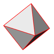
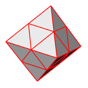
The compression process quantizes a normal as follows. It first divides the unit sphere into eight octants. The signs of the 3 coordinates of the normal determines the octant and the first 3 bits of the quantized normal. Then the triangle determined by the 3 canonical vectors of the octant is recursively subdivided NSUBDIVISION times. The triangle that the normal belongs to at each level of subdivision is represented by two bits in the quantized normal. The decompression process approximates the normal with the normalized centroid of the triangle determined by the quantized normal. Each quantized normal requires 3+2*NSUBDIVISION bits.
 |
 |
 |
    CGD
      VTREE
      UNSIGNEDINT NTCOMPONENTS
      TCOMPONENT[NTCOMPONENTS]
    VTREE
      UNSIGNEDINT NVRUNS
      UNSIGNEDINT BITSPERVRUNLENGTH
      VRUNS
      UNSIGNEDINT NDATARECORDS
      DATARECORD[NDATARECORDS]
    VRUNS
      VRUN[NVRUNS]
      VRUNSPADDING
    VRUN
      BIT                    VLAST
      BIT[BITSPERVRUNLENGTH] VLENGTH
      BIT                    VLEAF
Since the length in bits of each VRUN is equal to BITSPERVRUNLENGTH+2, the
length in bytes of VRUNS is (NVRUNS*(BITSPERVRUNLENGTH+2)+7)/8.  The field
VRUNSPADDING represents the number of bits necessary to reach a byte
boundary after the last VRUN.
    TCOMPONENT
      UNSIGNEDINT NTTREES
      TTREE[NTTREES]
    TTREE
      UNSIGNEDINT NTRUNS
      UNSIGNEDINT BITSPERTRUNLENGTH
      HAS
      if(HASLJUMPS | HASRJUMPS) {
        UNSIGNEDINT BITSPERJUMP
      }
      TRUNS
      UNSIGNEDINT NTDATARECORDS
      DATARECORD[NTDATARECORDS]
    HAS
      BIT    HASPOLYGONS
      BIT    HASINVLOR
      BIT    HASINVROR
      BIT    HASINVLJUMPS
      BIT    HASINVRJUMPS
      BIT[3] HASPADDING
    TRUNS
      TROOT
      TRUN[NTRUNS]
      TRUNSPADDING
    TROOT
      if(HASINVLOR) {
        BIT INVLOR
      }
      if(HASINVROR) {
        BIT INVROR
      }
      BIT[BITSPERTROOTID] TROOTID
      BIT TLEAF
      if(HASLJUMPS) {
        BIT HASLJUMP
	if(HASLJUMP) {
	  BIT[BITSPERJUMP] LJUMP
	}
      }
      if(HASRJUMPS) {
        BIT HASRJUMP
	if(HASRJUMP) {
	  BIT[BITSPERJUMP] RJUMP
	}
      }
If the vertex tree has V nodes, the bounding loop has 2V-2 nodes.
BITSPERTROOTID is the number of bits required to represent the number 2V-2.
TROOTID is the index of a bounding loop node.
Each of the NTRUNS TRUNs may be of different length.
    TRUN
      if(HASINVLOR) {
        BIT INVLOR
      }
      if(HASINVROR) {
        BIT INVROR
      }
      BIT[BITSPERTRUNLENGTH] TLENGTH
      BIT TLEAF
      if(HASLJUMPS) {
        BIT HASLJUMP
	if(HASLJUMP) {
	  BIT[BITSPERJUMP] LJUMP
	}
      }
      if(HASRJUMPS) {
        BIT HASRJUMP
	if(HASRJUMP) {
	  BIT[BITSPERJUMP] RJUMP
	}
      }
      BIT[TLENGTH-1] MARCHING
      if(HASPOLYGONS) {
        BIT[LENGTH] ISPOLYGONEDGE
      }
The ISPOLYGONEDGE bits indicates which of the marching edges of the
current TRUN are edges of the polygonal mesh, and which ones are
not. The cut edges, i.e., the edges of the vertex tree, must all be
edges of the polygonal mesh.
The field TRUNSPADDING represents the number of bits necessary to
reach a byte boundary after the last TRUN.
    DATARECORD
      UNSIGNEDINT DATATYPE
      UNSIGNEDINT ENCODINGTYPE
      UNSIGNEDINT NNODES
      QUANTIZATIONPARAMETERS
      ENCODINGPARAMETERS
      UNSIGNEDINT NBYTESDATA
      DATA
The field DATATYPE may have the following values:
    0 COORDINATES
    1 NORMALS
    2 COLORS
    3 TEXTURECOORDINATES
    4 COORDINATEINTERPOLATOR
    5 NORMALINTERPOLATOR
    6 COLORINTERPOLATOR
Other values are reserved for future use, and should be considered as
an error.
The field ENCODINGTYPE may have the following values:
    0 QUANTIZED
    1 HUFFMAN
Other values are reserved for future use, and should be considered as
an error.
    QUANTIZATIONPARAMETERS
      if(DATATYPE==NORMALS || DATATYPE==NORMALINTERPOLATOR) {
        UNSIGNEDINT NSUBDIVISION
	if (DATATYPE==NORMALINTERPOLATOR) {
        UNSIGNEDINT NKEYS
	}
      } else {
        UNSIGNEDINT NBITSPERVALUE
	if (DATATYPE==COORDINATEINTERPOLATOR ||
	    DATATYPE==COLORINTERPOLATOR      ) {
        UNSIGNEDINT NKEYS
	}
        if(DATATYPE==COORDINATES     ||
	   DATATYPE==COLORS          ) {
          FLOAT[3] VROOT
          FLOAT[3] BBOXCENTER
        } else if(DATATYPE==TEXTURECOORDINATES) {
          FLOAT[2] VROOT
          FLOAT[2] BBOXCENTER
	} else if(DATATYPE==COORDINATEINTERPOLATOR ||
	          DATATYPE==COLORINTERPOLATOR      ) {
          FLOAT[3*NKEYS] VROOT
          FLOAT[3*NKEYS] BBOXCENTER
        } else {
          FLOAT[2*NKEYS] VROOT
          FLOAT[2*NKEYS] BBOXCENTER
	}
	FLOAT BBOXSIDE
	UNSIGNEDINT NLAMBDA
	FLOAT[NLAMBDA] LAMBDA
	SIGNEDINT MINERROR
      }
    ENCODINGPARAMETERS
      UNSIGNEDINT NBITSPERERROR
      if(ENCODINGTYPE==HUFFMAN) {
        UNSIGNEDINT TABLETYPE
        if(TABLETYPE==GAUSS) {
	  FLOAT MEAN
	  FLOAT VARIANCE
	} else {
          if(TABLETYPE==SHORT) {
	    UNSIGNED ATTACHTOKEY
	  }
	  UNSIGNEDINT NTABLE
	  TABLE
        }
The field TABLETYPE may have the following values:
    0 GAUSS
    1 LONG
    2 SHORT
Other values are reserved for future use, and should be considered as
an error.
    TABLE
      TABLEENTRY[NTABLE]
      TABLEPADDING
    TABLEENTRY
      BIT[NBITSPERERROR+1] TABLEENTRYLEFT
      BIT[NBITSPERERROR+1] TABLEENTRYRIGHT
The field TABLEPADDING represents the number of bits necessary to
reach a byte boundary after the last TABLEENTRY.
The decompression algorithm as described in above is not fully and completely specified. Among other things, some of the quantization and encoding steps must be specified in more detail. In a future draft of this document we will include a pseudo-code description of the decompression algorithm to remove the remaining uncertainties.
[
IBM Research |
VRML |
3DIX
]
[
RS/6000 |
IBM home page |
Order |
Search |
Contact IBM |
Help |
(C) |
(TM)
]